
Hydraulic Press
The hydraulic press is used to shape the plastic material by opening, closing and maintaining pressure in the molds.
1. General overview
1.1. Introduction
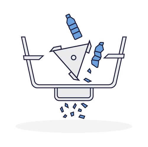
The hydraulic press is a machine for shaping the molten plastic coming out of the Extruder or the Sheet oven. The hot viscous plastic material is placed in a mold fixed to the hydraulic press The jacks that compress it are activated and cause the molds to close. The pressurized plastic spreads around the mold until it cools and the plastic sets.
The role of the hydraulic press
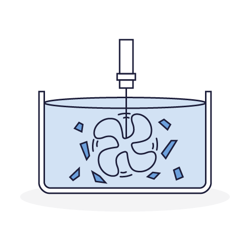
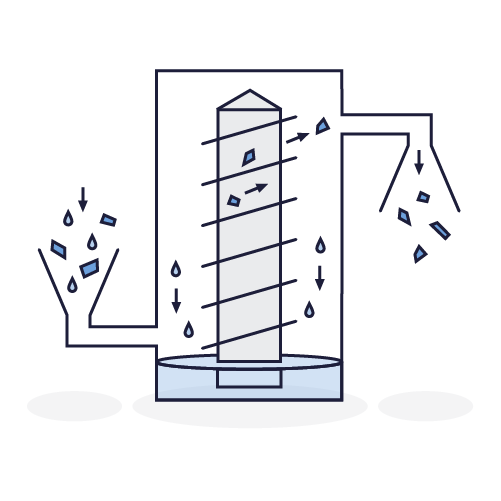
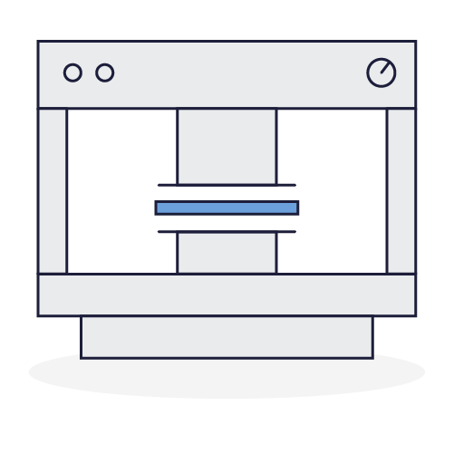
The hydraulic press is equipped with two plates, one is fixed and the other is mobile. Actuated by jacks, the movable plate guided by four columns approaches the fixed plate. The cylinders apply even pressure to the element between the plates.
The molds installed on the hydraulic press usually consist of two shells (fixed part and moving part) which are strongly pressed. The pressure exerted by the hydraulic press distributes the hot plastic over the entire footprint of the mold.
In industry, we often find injection molding systems. This technology is more complex and requires advanced technical knowledge. An injection molding machine allows a high production rate and a precise quality of the produced parts. However, we made the choice of a hydraulic press because it is a machine which is, throughout the world, much more widespread, less expensive; therefore easier to obtain and to use.
1.2. The hydraulic press on board the Plastic Odyssey
The hydraulic press that we have chosen to take on board is a machine that can be found on the market.
Why this choice? We have no choice but to add this machine into our production system due to its simplicity of design and use.
The hydraulic press that we have on board is equipped with two large plates. These allow us to accommodate large molds, for example to make sheets.
2. Technical guide
2.1 Technical datasheet
General characteristics
Motorisation
Process
Economic and environmental
2.2. Connections and Sockets
Network Connections
Sockets
3. User guide
3.1. Preparation
Mandatory protection:

Coveralls

Safety shoes

Protective gloves

Safety glasses
Necessary Equipment:
- Clamping tools
- Set of keys
Good practices:
- Make sure that the workpiece is centered evenly and rests firmly on the pressure plate so that it cannot be projected during the working process
- Put the presses safety guards, that protect against the risk of projection, in place
- Do not reach into the device while it is in operation
- No springs, or other objects which could be projected from the press, should be compressed
- No object that could break during the working process should be compressed
- Do not use the press beyond its capacity
Ensure you have read the information specified in the information sheets: Jobsite Information Sheet, Safety Sheet
Verification
Before any use, visually check the mechanical condition. Periodically check the condition of the equipment (see maintenance sheet).
3.2. Usage

- Place the mold on the lower plate
- Center the mold on the plate to guarantee a central distribution of the load
- Check that the plates are clear and that no object is placed on the lower plate

- Start the hydraulic pump by pressing the start button

- Raise the lower plate by simultaneously pressing the cycle start buttons
- Raise the lower tray pistons until the mold closes

- Lower the lower plate to the bottom by pressing the descent button and when the cooling time has elapsed

- Actuate the ejectors to release the part from the mold
- Return the ejectors and clean the mold
4. Safety
4.1. Training
The operators who interact with the hydraulic press must be aware of and respect the information relating to the use of the machine, the risks of using the machine, and the appropriate safety practices.
4.2. Risks
- Crushing of upper limbs
- Projecting objects
- Cuts due to handling rough chips
4.3. Operator behavior
- Put in place the existing protectors
- Do not reach into the device while it is in operation
- No springs or other objects which could be ejected or broken should be compressed
- Do not use the press beyond its capacity
4.4. Personal protective equipment
- Safety shoes are compulsory throughout the workshop and around all the machines.
- The operator has to handle plastic chips which can be rough, protective gloves are therefore mandatory to handle the chips safely.
- Projectiles may occasionally be ejected from the press, therefore protective goggles must be worn.
- The operator must wear suitable work clothes.
4.5. Safety features
Safety features guarantee the safety of operators on the hydraulic press. Make sure they are correctly installed before use:
- The multibeam laser curtain protects the operator and third parties by detecting parts of the human body that enter the dangerous zone.
- Guards are installed to prevent side and rear access to hazardous areas.
4.6. Work zone
A work zone around the machine is defined by a marking on the ground.
Access near the machine, whilst it is in operation, is permitted only to trained and equipped operators.
4.7. Jobsite information Sheet
The hydraulic press is equipped with a Jobsite Information Sheet which includes all the information necessary for the use of the machine in good safety conditions. It must be positioned in view of all operators using the hydraulic press.
4.8. Verification/Maintenance
Preventive and corrective maintenance activities must only be carried out by a person trained for this purpose. Each intervention must be recorded in order to keep a history of the maintenance actions carried out.
5. Cleaning and Maintenance
5.1. Maintenance schedule
Day to day
Weekly
Monthly
Yearly
5.2. Cleaning schedule
Day to day
Weekly
Monthly
Yearly
5.3. Intervention protocol
Before carrying out any maintenance, adjustment or repair intervention requiring partial or complete dismantling of parts of the shredder, it is necessary to follow these protocols.
Electrical
- Set the power button to Off
- Activate the emergency stop button, and if accessible, switch off the main power
- Mechanically block the power button with a padlock
- Check the absence of voltage on each of the active conductors (including the neutral) using a specially designed VAT device.
Hydraulic
- Close the valves
- Dissipate, purge or drain the oil and bring the area to atmospheric pressure
- If necessary, mechanically block the valves using padlocks or pins
- Check that there is no flow
Mechanical
- Wait for the rotor and the fan to stop completely