
Compactor
The compactor makes it possible to compress a set of waste to reduce its volume.
1. General overview
1.1. Introduction
If it is not recycled on site, the previously sorted waste can be sold and transported to specialized industries. In order to optimize the transport process and increase the quantity of material loaded, it may be necessary to form bales. By using a compactor, the waste is transformed into consistently shaped bales which makes it possible to reduce the cost linked to the transport of bulk materials.
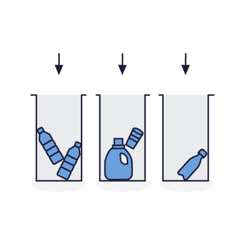
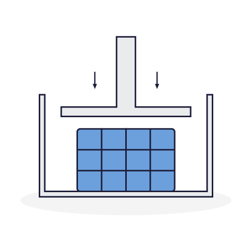
The role of the compactor
The compactor makes it possible to compress waste to reduce its volume. Waste, in the form of bales, can be sold to collection centers or to specialists in the recycling of certain materials. This is the case with plastic waste and also other materials such as cardboard, paper and aluminum. Packaged waste in the form of bales, can be stored to avoid mounds, skips and overflowing garbage cans.
The compactor consists of a rectangular frame in which the sorted waste is deposited. A jack makes it possible to lower a plate, compressing this waste. Strings wrap around the bale to hold the waste in place. This solution facilitates the transportation and storage of waste.
1.2. The compactor on board the Plastic Odyssey
The on-board compactor is a machine that can be found on the market. We chose to source an off-the-shelf compactor because we have no innovative value to add to this machine in recognition of its simplicity of design and use.
2. Technical guide
2.1 Technical datasheet
General characteristics
Motorisation
Process
Economic and environmental
2.2. Connections and Sockets
Network Connections
Sockets
3. User guide
3.1. Preparation
Mandatory protection:

Coveralls

Safety shoes

Protective gloves
Necessary Equipment:
- A reel of textile strip
- A sack barrow
- A pole for threading (Supplied)
Good practices:
- Do not reach into the device while it is in operation
- Do not use or fill the compactor beyond its capacity
- Ensure you have read the information specified in the information sheets: Jobsite Information Sheet, Safety Sheet
Verification
Before any use, visually check the mechanical condition. Periodically check the condition of the equipment (see maintenance sheet).
3.2. Usage
- The compacting plate is in the high position
- Open both compactor doors
- Pull the strip through the compaction chamber through the openings in the ejection door
- Make a loop and lock the knot in the groove provided for this purpose
- Use the supplied pole to push the strap down into the slots and out through the back of the chamber
- Close the lower door
- Load the compactor with the waste
- Once the compaction chamber is full, close the upper door
- Press the green start button
- Position the compaction lever down
- To return the compaction plate to its initial position, press the green button and position the compaction lever upwards
- Repeat the filling and compacting operations until the desired bale size is obtained
- Return the compacting plate to the high position
- Open the upper door
- Use the threading rod to pull the strapping bands through the rear slots
- Pass the strapping bands over the bale and bring them out at the front of the press
- Cut the strapping strips to a length sufficient to reach the other ends attached to the attachment points which are located at the bottom of the lower door.
- Wind the excess tape on the spools
- Pass each link in their respective groove
- Close the door and start the compacting cycle
- Stop the baler when the compacting plate is in the down position
- Tie the textile ties
- When the bale is tied off, close the top door and reassemble the compacting plate
- Open both doors
- Use the cart to extract the bale
4. Safety
4.1. Training
The operators who interact with the compactor must be aware of and respect the information relating to the use of the machine, the risks of using the machine, and the appropriate safety practices.
4.2. Risks
- Crushing when handling bales and closing doors
- Cuts due to waste handling
4.3. Operator behavior
- Do not open the doors while the compactor is operating
- Use the trolley provided to handle the waste bales
4.4. Personal protective equipment
- Safety shoes are compulsory throughout the workshop and around all the machines.
- The operator has to handle sharp materials, so protective gloves are required to handle them without risk.
- The operator must wear suitable work clothes.
4.5. Safety features
Safety features guarantee the safety of operators of the compactor. Make sure they are correctly installed before use:
- Opening the doors causes the compaction plate to stop
4.6. Work zone
A work zone around the machine is defined by a marking on the ground.
Access near the machine, whilst it is in operation, is permitted only to trained and equipped operators.
4.7. Jobsite information Sheet
The shredder is equipped with a Jobsite Information Sheet which includes all the information necessary for the use of the machine in good safety conditions. It must be positioned in view of all operators using the compactor.
4.8. Verification/Maintenance
Preventive and corrective maintenance activities must only be carried out by a person trained for this purpose. Each intervention must be recorded in order to keep a history of the maintenance actions carried out.
5. Cleaning and Maintenance
5.1. Maintenance schedule
Day to day
Weekly
Monthly
Yearly
5.2. Cleaning schedule
Day to day
Weekly
Monthly
5.3. Intervention protocol
Before carrying out any maintenance, adjustment or repair intervention requiring partial or complete dismantling of parts of the shredder, it is necessary to follow these protocols.
Electrical
- Set the power button to Off
- Switch off the main power
- Mechanically block the power button with a padlock
- Check the absence of voltage on each of the active conductors (including the neutral) using a specially designed VAT device.
Mechanical
- Wait for the fan to stop completely
- Visually check for dissipation of motor force and immobilization of moving parts