

Washing Tank
Post-consumer or industrial waste is generally pre-used and contaminated with different types of residues. The presence of dust, dirt or metal makes recycling complex.
1. General overview
1.1. Introduction
The purpose of the washing tank is to separate the impurities from the plastic waste. These impurities are incompatible with recycling machines and can cause problems during the stages of plastic processing. Improper washing causes defects on the new objects it is used to create.
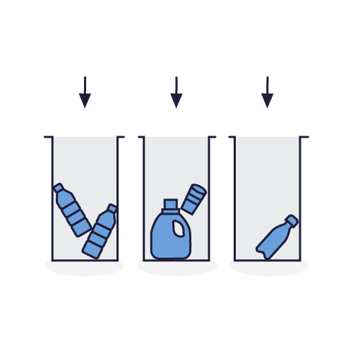
The plastic that gets washed is in the form of chips as a result of shredding beforehand.
This step is necessary to ensure washing of all inaccessible surfaces, such as the inside of a bottle.
Washing is an essential step in treating dirty waste. It makes it possible to integrate this waste, which is currently barely recycled in industry, into the recycling process and thus increase its recovery rates.
The role of the washing tank
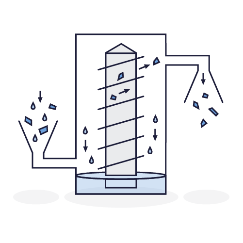
The role of the washing tank is similar to the action of a washing machine. The plastic chips and water contained in a tank are mixed by a system of rotating blades. The friction between the chips caused by the movement of the water helps loosen impurities.
These impurities, which have a higher density than water than water, will sink and settle at the bottom of the tank. In contrast, the targeted plastics (PP, HDPE, LDPE), with a lower density than than water, float on the surface of the washing tank. They are then removed from the tank and drained.
1.2. The washing tank on board the Plastic Odyssey
The washing tank was designed in the Plastic Odyssey workshop in Marseille. It is the result of numerous visits to recycling centers and meetings, particularly in Cairo, Burkina Faso and Thailand. These exchanges allowed us to acquire knowledge and benefit from feedback to design a proven and functional system on a semi-industrial scale.
The on-board washing tank is low-tech, efficient, easy to use and easily adaptable to the dimensions of any recycling workspace.
1.3. Component Overview
The main components that make up the washing tank are:

- Tank
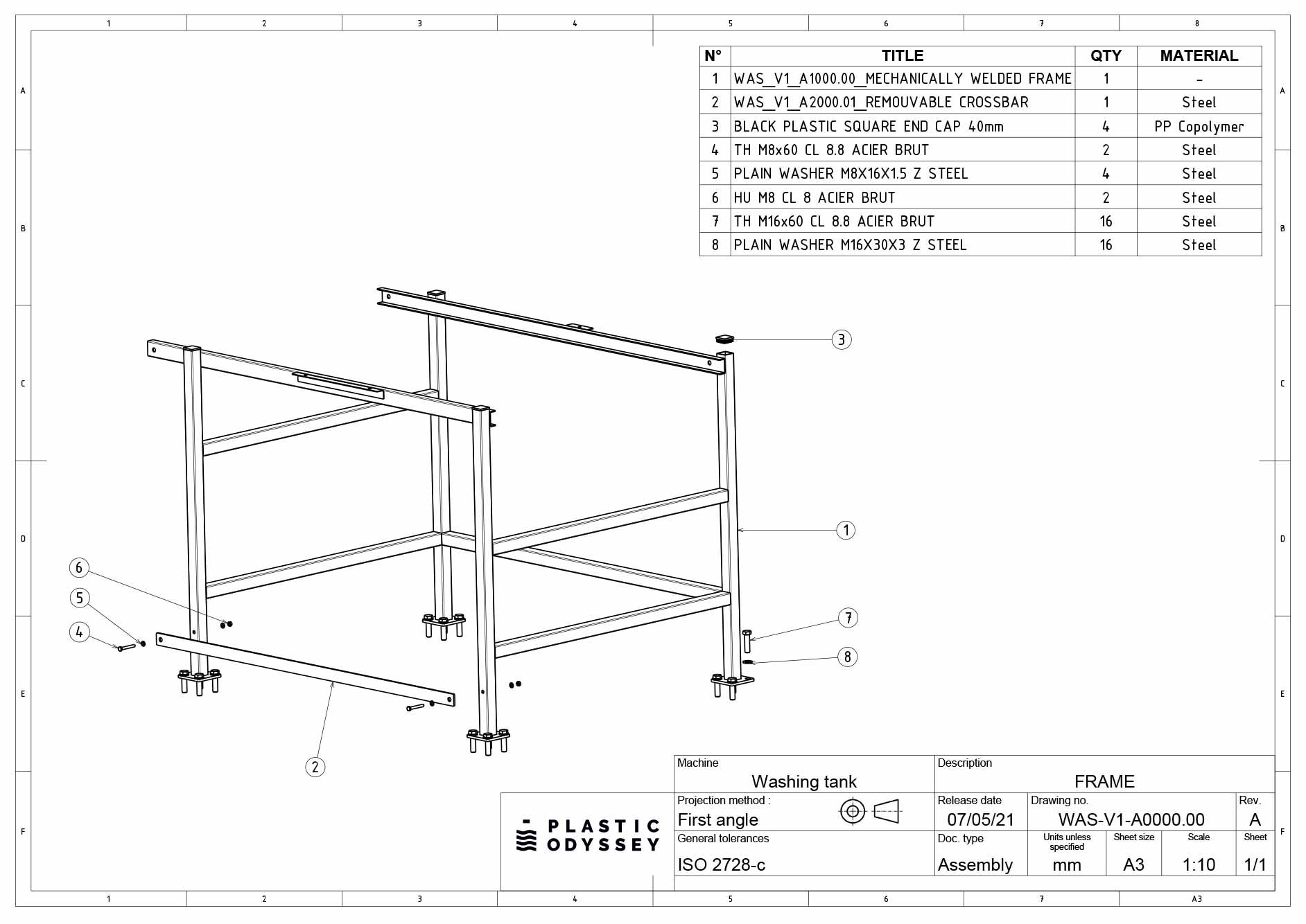
- Frame
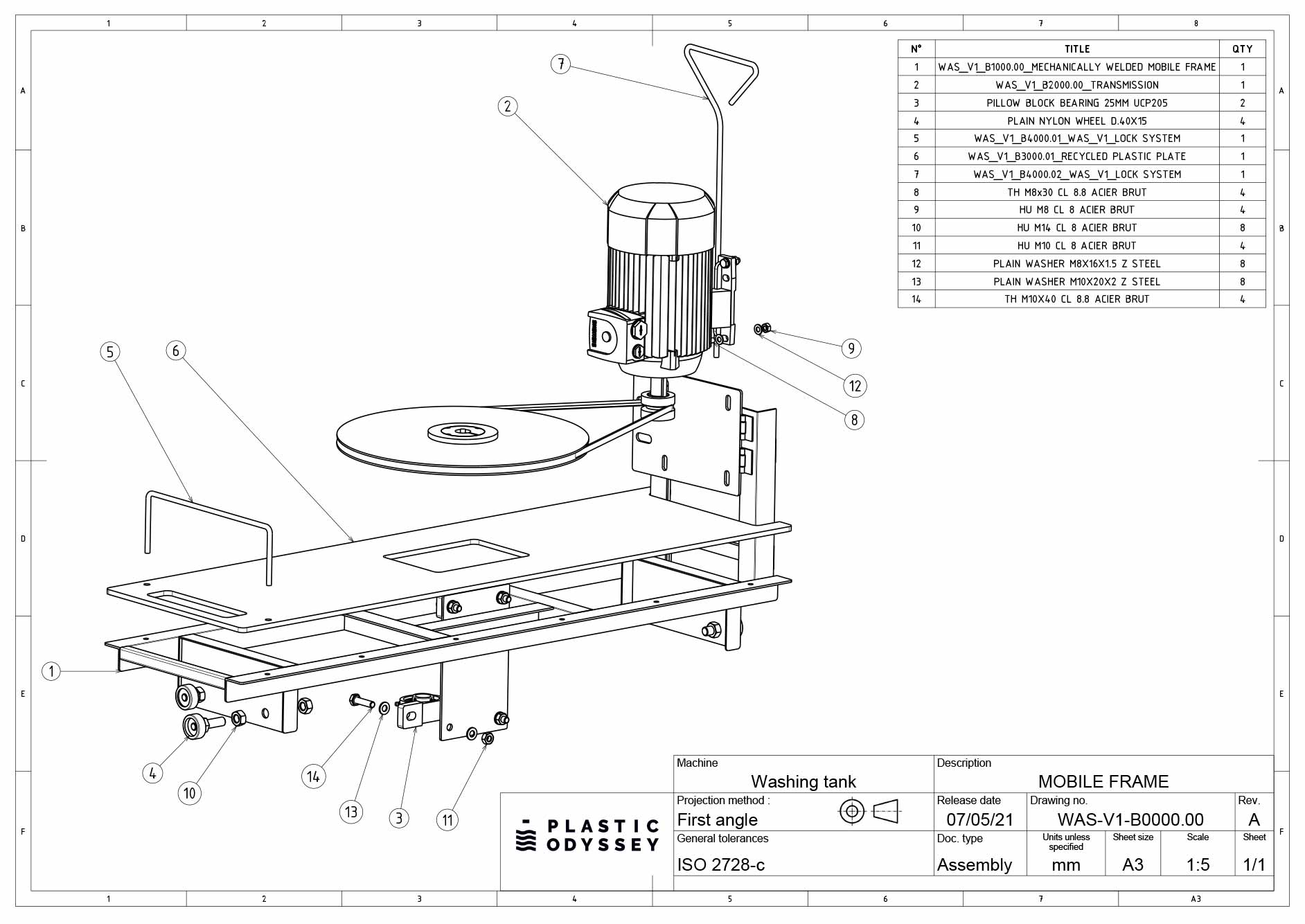
- Carriage
- Transmission
- Mixer shaft
2. Technical guide
2.1 Technical datasheet
General characteristics
Motorisation
Process
Economic and environmental
Wastewater from the washing process is collected, filtered and recycled, which significantly reduces water consumption.
Manufacturing
The washing tank has been developed to meet the following objectives: to be accessible, simple to build, simple to use and inexpensive. That is to say with standard and / or recoverable materials, without electronics.
2.2. Connections and Sockets
Network Connections
Sockets
3. User guide
3.1. Preparation
Mandatory protection:

Protective gloves

Safety shoes

Protective gloves

Safety glasses
Necessary Equipment:
- A water pipe
- Screening cloth
- A drainage system
- Bucket
- A filter for wastewater
Good practices:
- Lock the carriage before starting the motor
- Check that the discharge valve is closed
- Only move the carriage using the handle provided
- Do not spin the blades in an empty tank
- Do not put your hands in the tank during washing
- Treat polluted water
- Ensure you have read the information specified in the information sheets: Jobsite Information Sheet, Safety Sheet
Verification
Before any use, visually check the mechanical condition. Periodically check the condition of the equipment (see maintenance sheet).
3.2. Usage

- Fill or adjust the water level in the tank up to the mark indicated on the wall of the tank and on the Jobsite Information Sheet
- If the plastic type is changed between two washing cycles, check that there is no ground shredded on the surface of the water
- Do not mix different types of plastic. 1 wash cycle = 1 type of plastic

- Using the bucket, pour the ground plastic material into the tank (PP, HDPE, LDPE)
The quantity of plastic should be adjusted according to its cleanliness. For visually clean waste, wash around 10 KG of shredded material per cycle. Conversely, for heavily soiled shredded material, reduce the quantity by half.

- Place the carriage in the center and lock its position

- Start the engine by pressing the ON button
Duration of the washing cycle: approx. 5 min - Stop washing by pressing the OFF button
- Leave to stand for a few minutes while the impurities flow out and the ground material rises to the surface
Repeat this process if necessary.

- Unlock the carriage

- Move the carriage to the end of the tank
- Use the screening cloth to extract the ground material from the surface and place it in the drainage system
- Leave the ground material to drain for a few minutes
- Store or transport the ground material to the next step; the Centrifuge
4. Safety
4.1. Training
The operators who interact with the wash tank must be aware of and respect the information relating to the use of the machine, the risks of using the machine, and the appropriate safety practices.
4.2. Risks
- Crushing of fingers linked to the movement of the carriage on the guide rail
- Shock due to the projection of an object and the collision between the blades and the tank
- Winding / entanglement of clothes or objects due to the rotating system
- Projection of plastic chips
- Cuts due to handling rough chips
4.3. Operator behavior
- Do not lean over the wash tank
- Do not put your hands in the wash tank when the blades are turning
4.4. Personal protective equipment
- Safety shoes are compulsory throughout the workshop and around all the machines.
- The operator has to handle plastic chips which can be rough, protective gloves are therefore mandatory to handle the chips safely.
- Plastic chips can occasionally be violently thrown, therefore protective goggles must be worn.
- The operator must wear suitable work clothes.
4.5. Safety features
Safety features guarantee the safety of operators on the washing tank. Make sure they are correctly installed before use:
- The two end stops are fixed to the frame rail to prevent the rotating blades from coming into contact with the tank.
- The locking system between the trolley and the frame is put in place before the washing tank is started.
- The belt guard is correctly positioned.
- The presence of a handle to move the mobile cart.
4.6. Work zone
A work zone around the machine is defined by a marking on the ground.
Access near the machine, whilst it is in operation, is permitted only to trained and equipped operators.
4.7. Jobsite information Sheet
The washing tank is equipped with a Jobsite Information Sheet which includes all the information necessary for the use of the machine in good safety conditions. It must be positioned in view of all operators using the shredder.
4.8. Verification/Maintenance
Preventive and corrective maintenance activities must only be carried out by a person trained for this purpose. Each intervention must be recorded in order to keep a history of the maintenance actions carried out.
5. Cleaning and Maintenance
5.1. Maintenance schedule
Day to day
Weekly
Monthly
Yearly
5.2. Cleaning schedule
Day to day
Weekly
Monthly
Yearly
5.3. Intervention protocol
Before carrying out any maintenance, adjustment or repair operation requiring partial or complete disassembly of parts of the washing tank, it is necessary to follow these protocols.
Electrical
- Set the power button to Off
- Activate the emergency stop button, and if accessible, switch off the main power
- Mechanically block the power button with a padlock
- Check the absence of voltage on each of the active conductors (including the neutral) using a specially designed VAT device
Hydraulic
- Close the valves
- Dissipate, purge or drain the water and bring the area to atmospheric pressure
- If necessary, mechanically block the valves using padlocks or pins
- Check that there is no flow
Mechanical
- Wait for the rotors and fans to come to a complete stop
- Uncouple the belts
- Mechanically block the rotor
- Visually check for dissipation of motor force and immobilization of moving parts